How to Detect RJ45 Patch Panel Faults with a LAN Tester
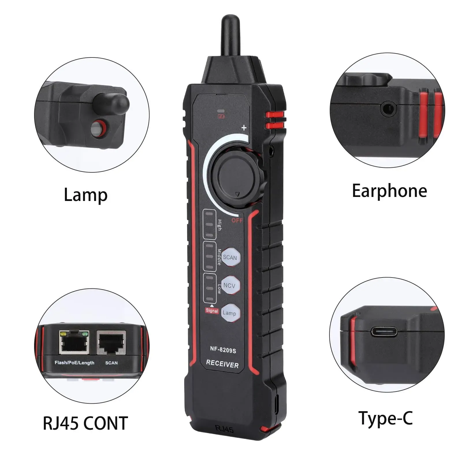
If you need a LAN cable tester for patch panel faults, the short answer is this: use a tester that can verify wiremap, continuity, split pairs and, ideally, cable length, then test from the patch panel port to the wall outlet or device end. This quickly shows whether the fault is in the patch panel termination, the horizontal cable run, or the patch lead.
TL;DR: A LAN cable tester helps you diagnose patch panel faults by checking for open circuits, shorts, crossed pairs, reversed pairs and split pairs. For UK installations, start by isolating the link, test each port with a remote unit, compare results against T568A or T568B pinouts, and re-terminate any suspect punches. Based on our testing, wiremap and continuity checks solve most patch panel fault-finding jobs far faster than swapping cables at random.
Why use a LAN cable tester for patch panel faults?
A patch panel fault can look like a dead network socket, intermittent speed drops or a link that negotiates at 100Mb instead of 1Gb. However, the real problem may be an open pair, poor punch-down termination or a split pair hidden behind an apparently tidy cabinet. A proper LAN cable tester gives you a clear result instead of guesswork.
According to common UK structured cabling practice, every permanent link should be tested after installation and again during fault-finding if service quality changes. Therefore, if you are tracing unreliable office ports, classroom outlets or cabinet terminations, a dedicated tester is usually the quickest place to start.
Based on our testing, the most useful features for patch panel troubleshooting are:
- Wiremap testing for pin-to-pin accuracy
- Continuity checks for broken conductors
- Detection of shorts, reversals and crossed pairs
- Split pair detection for performance-related faults
- Length measurement to help identify where a break may be
- Tone tracing for unlabelled ports and bundled cabling
What faults can a LAN cable tester detect on a patch panel?
A good LAN cable tester can detect several common faults that appear at patch panels and RJ45 outlets. In practice, these are the issues most likely to affect day-to-day network performance.
Can it detect an open circuit?
Yes. An open circuit means one or more conductors are not making contact from end to end. This often happens where a wire has not been fully seated into the IDC terminal on the rear of the patch panel or has pulled loose at the outlet. As a result, devices may fail to link at all.
Can it detect a short circuit?
Yes. A short occurs when two conductors touch each other unintentionally. This can happen after poor termination work, damaged insulation or over-tight handling in a cabinet. Consequently, communication on that link will be unstable or completely absent.
Can it detect crossed or reversed pairs?
Yes. If pins are terminated in the wrong order at one end, the tester will show a wiremap error. This is especially helpful when one end has been punched as T568A and the other as T568B without intention.
Can it detect split pairs?
On better testers, yes. A split pair is more subtle than a simple miswire: continuity may appear present, but the conductors are paired incorrectly. Therefore, you may still get some connectivity while suffering poor throughput, packet loss or failure to achieve Gigabit Ethernet speeds.
Can it identify cable length problems?
If your tester includes length measurement or TDR-style functions, it can estimate how long the run is and sometimes indicate how far along the fault lies. This is particularly useful when diagnosing hidden damage in walls or ceiling voids.
How do you test an RJ45 cable connected through a patch panel?
If you are wondering how to test an RJ45 cable through a patch panel properly, follow this sequence. It reduces false assumptions and helps isolate whether the fault sits in the port, cabling run or patch lead.
- Disconnect live equipment first. Remove the link from switches and end devices before testing. If PoE may be present, check your tester supports that environment safely.
- Identify both ends of the link. One end will usually be the patch panel port; the other may be a wall outlet or device-side jack.
- Connect the main unit at the patch panel. Plug into the suspect port using a known-good patch lead if required.
- Attach the remote unit at the far end. This completes an end-to-end wiremap test across the installed link.
- Run wiremap and continuity tests. Check for opens, shorts, reversals and crossed pairs first because these are common after re-termination work.
- Review split pair results if available. If users report slow speeds rather than total failure, this step matters even more.
- Measure length if supported. An unusual reading can point to damage part-way along the run or an unexpectedly routed cable path.
- Retest after re-punching suspect terminations. If any pair fails intermittently when moved slightly at the rear of the panel or module, re-terminate it fully.
In addition, check that both ends follow the same wiring standard. In UK commercial networks this is commonly T568B, although either T568A or T568B can be used as long as both ends match consistently across the installation.
Why is my patch panel port not working?
A non-working patch panel port usually comes down to one of a few causes. Firstly, there may be an incomplete punch-down where one conductor has not seated correctly into its IDC slot. Secondly, wires may have been arranged in the right colours but punched into incorrect pin positions. Thirdly, there could be physical damage from tight bends, crushed cable jackets or poor strain management inside the cabinet.
The issue is not always inside the panel itself either. For example:
- The wall outlet may be miswired
- The horizontal run may be damaged above ceilings or under floors
- The patch lead between switch and panel may be faulty
- The switch port may be disabled or negotiated incorrectly
- The labelling may simply point you to the wrong port
This is why using a LAN cable tester for patch panel faults is so effective: it separates cabling problems from active equipment issues before you spend time replacing hardware unnecessarily.
How do you find a faulty port on a patch panel?
The fastest method is systematic testing rather than trial and error. Start with user-reported ports first; then move outward from confirmed symptoms to likely causes. As a result, you avoid chasing unrelated cabinet clutter.
Step 1: Confirm which outlet matches which patch panel port
If labels are missing or unclear, use a tone generator and probe to trace each run accurately. This matters especially in older UK comms cupboards where moves and changes have accumulated over time.
Step 2: Test with known-good leads
A failed patch lead can mimic a bad fixed link. Therefore replace temporary cords with known-good ones before judging permanent cabling.
Step 3: Run an end-to-end wiremap test
This immediately reveals whether all eight conductors terminate correctly from cabinet to outlet.
Step 4: Inspect rear terminations visually
Look for untwisted pairs extending too far into termination points, loose jackets near strain relief areas and inconsistent colour placement against printed wiring guides on modules.
Step 5: Re-punch and retest
If one pair shows intermittent results or fails outright, re-terminate with an appropriate punch-down tool and retest straight away.
Based on our testing across typical office links, poor terminations remain one of the most common causes of “dead” ports after cabinet changes or expansions.